Maddie Hardware · Power
m-power
A 4 HP Eurorack power supply that runs from two isolated 12V wall adapters. It supplies +12V, −12V and +5V to the m-power bus or to a standard 16-pin busboard.
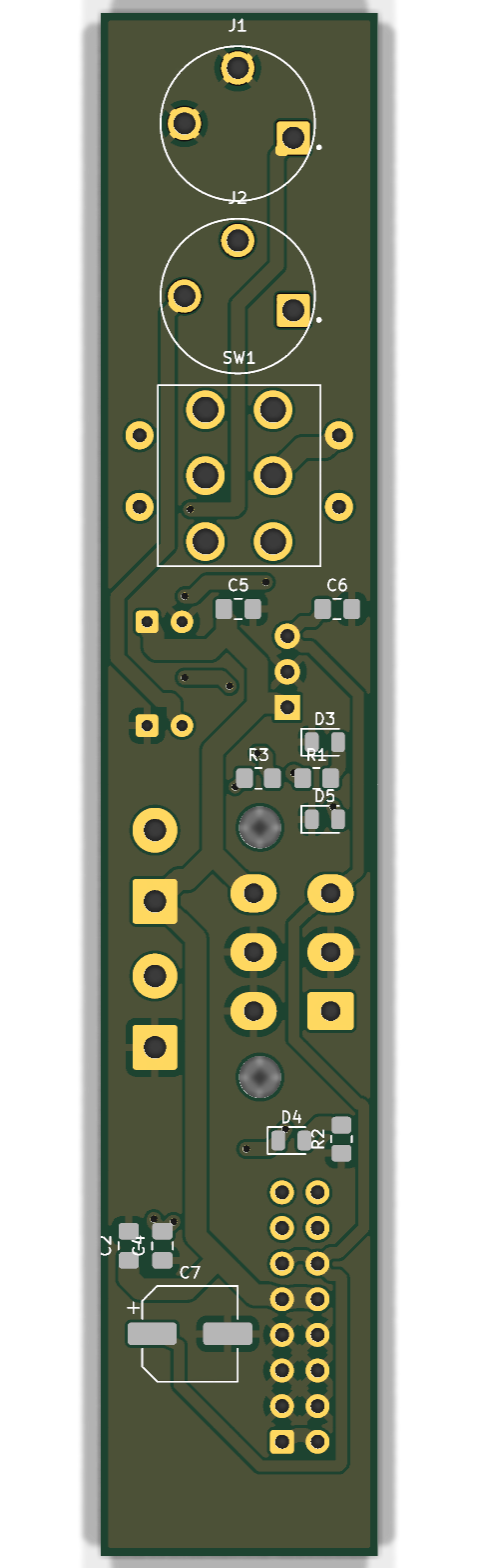
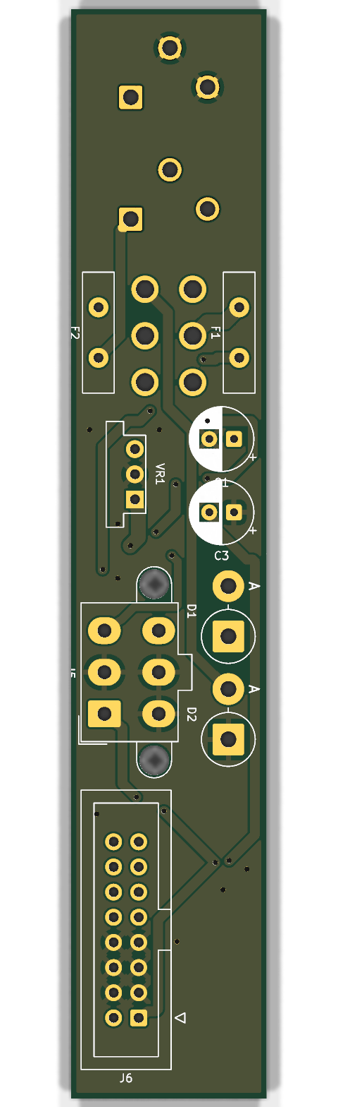
- Width
- 4 HP
- PCB
- 19.8 × 110 mm, 2 oz copper
- Depth
- ≈ 30–35 mm
- Input
- 2 × 12V DC, 2.1 mm, centre positive
- Outputs
- +12V · −12V · +5V (1.5 A)
- Connectors
- Mini-Fit Jr 2×3 · Eurorack 16-pin
Overview
m-power makes a bipolar Eurorack supply from two ordinary 12V wall adapters. Adapter A makes the +12V rail. Adapter B is isolated, so its positive side connects to ground and its sleeve becomes the −12V rail. A Murata OKI-78SR-5 module makes +5V from the +12V rail.
One toggle switch turns both adapters on and off together. An LED for each rail shows through a light pipe in the panel: white for +12V, pink for −12V and blue for +5V.
Parts are on both faces of the board. The large parts stand upright on the back, which is how the supply fits in 4 HP.
Status: this board is not finished. One net needs a hand-routed track before you export the Gerbers.
Outputs
Mini-Fit Jr 2×3 (J5) connects to the m-power bus:
| Pin | Rail | Pin | Rail |
|---|---|---|---|
| 1 | −12V | 4 | GND |
| 2 | GND | 5 | GND |
| 3 | +5V | 6 | +12V |
Eurorack 16-pin header (J6) uses the standard Doepfer pin map. Pins 1 and 2 are −12V (red stripe). The CV and gate pins are not connected.
Safety
- Use two isolated (Class II, double-insulated), regulated 12V adapters. They must be centre positive. Never use an earth-referenced adapter for input B.
- Use two adapters of the same type. If one adapter stops, the modules get only one rail.
- The rails are about 0.5 V below the adapter voltage, because each input has a series Schottky diode.
- Turn the power off before you connect or disconnect a cable.
Protection
- A reversed adapter cannot conduct, because of the series Schottky diode. The module stays dark.
- Each input has a 3 A resettable PTC fuse. If a cable shorts, the fuse trips. Remove the fault and let the fuse cool.
- There is no overvoltage clamp. A 15–19V adapter or an AC adapter puts that voltage on the rails. Check the adapter before you connect it.
Build notes
- Order the PCB with 2 oz outer copper. With 1 oz copper, the narrow tracks carry only about 2.4 A.
- Use the toggle switch C&K 7201SYCQE exactly. The Q (silver) contacts are rated 5 A. The B (gold) version is rated 0.4 VA and the rail current destroys it.
- The board has no mounting holes. The two barrel-jack bushings and the toggle bushing hold the panel.
- Measure the panel-to-PCB gap (about 9–11 mm) before you order the light pipes.
Smoke test
- Connect adapter A only and turn on the switch. The white LED comes on, and pin 6 of J5 reads +11.4 to +11.7 V.
- Connect adapter B. The pink LED comes on, and pin 1 reads −11.4 to −11.7 V.
- The blue LED comes on. J5 pin 3 and J6 pins 11/12 read 5.0 V.
- Test with one small module before you connect the whole case.
© 2026 Maddie Synths · MIT