Maddie Hardware · Power
JST Power Adapter
A small board that connects a 5-pin JST PH cable from the m-power bus to the power header of one module. One version fits 16-pin headers and one fits 10-pin headers.
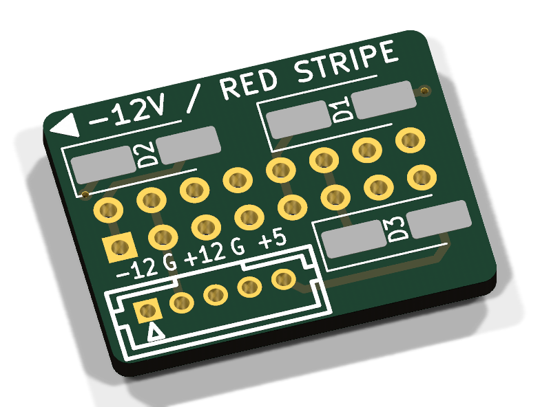
- 16-pin board
- 22.6 × 17.1 mm · ±12V, +5V
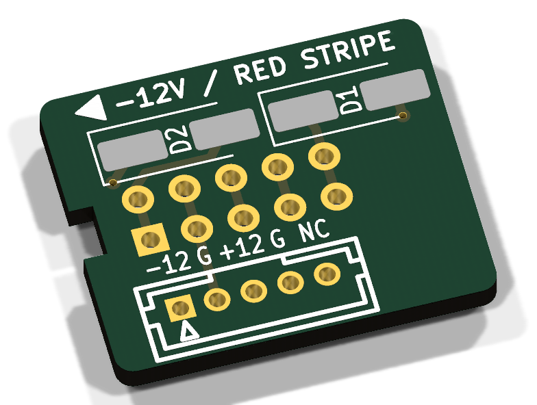
- 10-pin board
- 20.8 × 17.1 mm · ±12V
- Input
- JST PH 5-pin
- Protection
- SS34 Schottky on each rail
- Parts
- 3 per board (J1, J2, diodes)
Overview
Each adapter feeds one Eurorack module from a 5-pin JST PH cable. The cable plugs into the top of the board. A female socket on the bottom pushes straight down onto the power header of the module. Use it with the m-power bus.
- The 16-pin board supplies +12V, −12V and +5V.
- The 10-pin board supplies +12V and −12V. It does not use pin 5 of the JST header.
JST pinout
| Pin | 1 | 2 | 3 | 4 | 5 |
|---|---|---|---|---|---|
| Rail | −12V | GND | +12V | GND | +5V |
This is the same pin map as the busboard slots, so connect cable pin n to pin n.
Rev A boards: the revision is on the bottom silkscreen. Rev A has pins 1 and 3 the other way round. Cross the wires on pins 1 and 3 at one end of the cable. With a straight cable, the diodes block both rails and nothing is damaged.
Protection
Each rail goes through a series Schottky diode, so a cable with swapped wires cannot push current backwards into the module. The diodes drop about 0.35 V, so the +5V output is about 4.6 V. The board has no fuses: the busboard has a fuse on each slot.
16-pin board: if you plug it in the wrong way round, no current flows. The supply GND does not reach the module GND, so no rail has a return path.
10-pin board: if you plug it in the wrong way round, +12V and −12V change places. The board has a notch in its edge and a silkscreen arrow at the −12V end. Line up the arrow with the red stripe and check it before you apply power.
Parts
| Ref | Part | Qty 16-pin | Qty 10-pin |
|---|---|---|---|
| J1 | JST B5B-PH-K-S, 5-pin vertical | 1 | 1 |
| J2 | Female socket 2×8, 2.54 mm | 1 | – |
| J2 | Female socket 2×5, 2.54 mm, 8.5 mm | – | 1 |
| D1–D3 | SS34 Schottky, SMA | 3 | 2 |
Solder J2 on the bottom face. All other parts go on the top.
© 2026 Maddie Synths · MIT